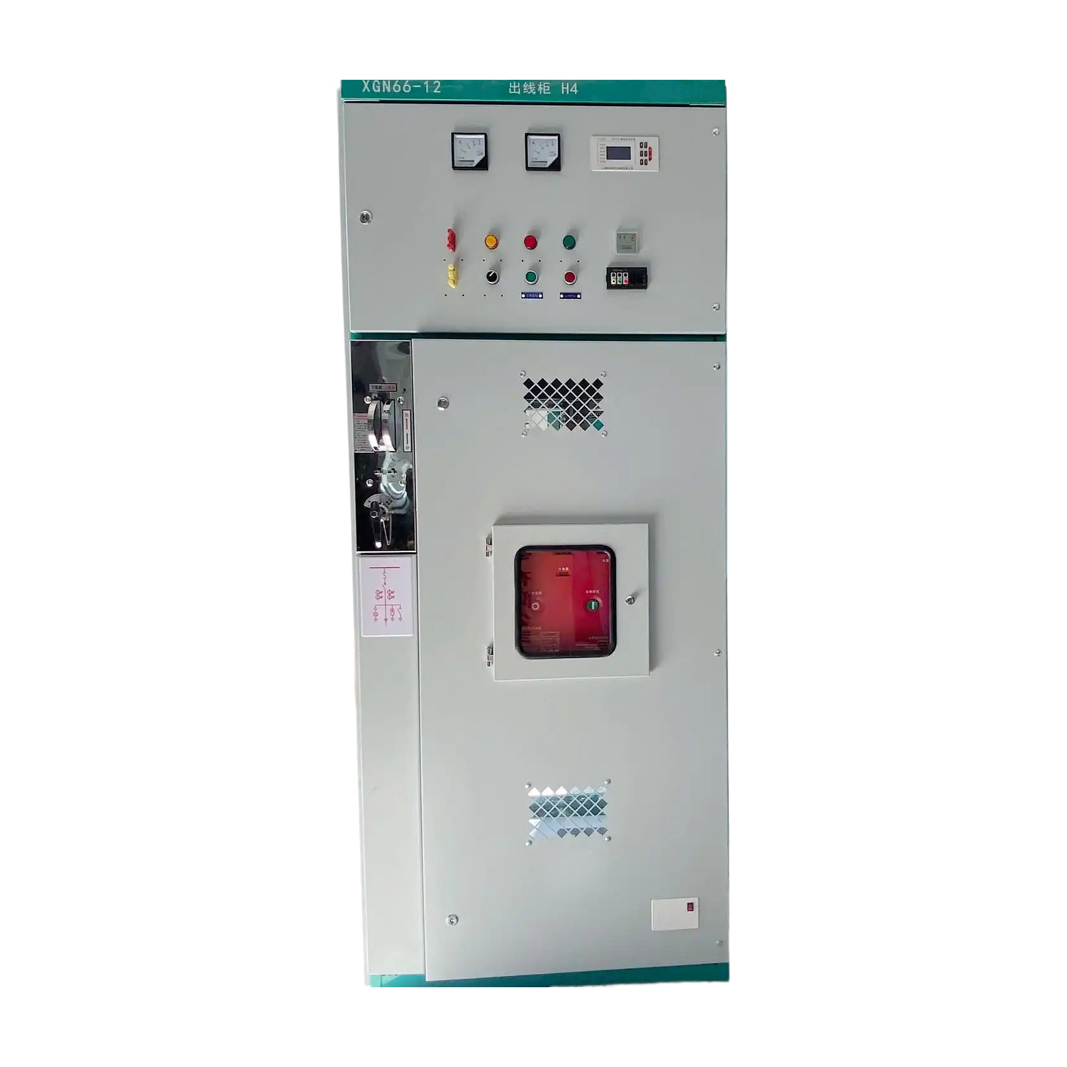
Modern electrical facilities demand reliable protection mechanisms and stringent personnel safety protocols. At the core of this power infrastructure is the metal enclosed switchgear. This critical assembly is engineered to isolate faults, control electrical loads, and protect sensitive downstream equipment. Specifying this equipment, however, goes far beyond merely selecting the correct voltage and amperage ratings.
Choosing the right compartment layout is a fundamental engineering decision. It directly impacts your facility footprint, maintenance downtime, operator safety, and overall capital budget. This article breaks down the different compartment layouts available for power distribution systems. By examining structural configurations, accessibility requirements, and vertical tiering options, engineers and facility managers can determine the exact layout for their project. Whether you are planning a compact urban substation or a sprawling continuous-manufacturing plant, mastering these physical configurations is essential for optimizing operational performance.
Structural Segregation: A standard unit is divided into four main sections: circuit breaker, busbar, cable, and low voltage control. This physical segregation is the primary defense for arc fault containment.
Maintenance Strategy: Withdrawable configurations minimize downtime through rapid modular replacement. Fixed layouts offer a cost-effective, space-saving alternative for facilities that can tolerate scheduled shutdowns.
Space Optimization: Front-access layouts and gas-insulated architectures provide superior footprint reduction. They achieve this without compromising mandatory dielectric safety clearances.
Voltage Dictates Design: Layout rules shift dramatically between low voltage and medium voltage systems. Higher electrical potentials demand stricter metallic segregation and larger air gaps.
Global urbanization and the exponential growth of edge computing are reshaping how we design electrical rooms. Facility managers no longer have the luxury of sprawling floor plans. Consequently, the power distribution sector is witnessing a massive shift toward high-density configurations. Real estate costs demand a smaller footprint. How do engineers achieve this without compromising safety? The answer lies in advanced compartmentalization, eco-friendly insulating gases, and smart thermal management.
Furthermore, modern layouts are increasingly integrating IoT sensors directly into the low voltage compartments. This allows for real-time thermal monitoring of busbar joints and breaker contacts. As predictive maintenance becomes the industry standard, the physical layout must accommodate these digital upgrades while maintaining strict isolation from high-voltage zones.
To select an appropriate layout, one must first understand the fundamental building blocks of the equipment. A typical assembly features distinct structural zones. This compartmentalization is not a mere manufacturing preference. It is a strict safety requirement defined by international standards like IEC 62271-200, designed to contain plasma expansion and protect maintenance personnel.
The circuit breaker compartment serves as the active heart of the system. It houses the primary switching device responsible for interrupting fault currents. Physical dimensions here are dictated by the size and insulation medium of the breaker. When a massive short-circuit hits, the mechanical violence is immense. Adequate ventilation and structural integrity are paramount. The metal enclosure must withstand severe dynamic forces and rapid pressure expansion without rupturing.
Main busbars distribute electrical power horizontally across multiple adjacent cubicles. Typically running along the top or middle rear of the structure, this section features robust metallic segregation in premium layouts. This prevents an arc fault from propagating into neighboring cubicles. Engineers must evaluate this space for proper phase-to-phase clearances. Standoff insulators located here must endure the severe thermal stresses generated by peak loads.
Incoming utility power cables and outgoing feeder cables terminate in this specific section. Depending on structural routing like top entry via trays or bottom entry via trenches, the compartment must provide ample physical space. Anyone who has wrestled with pulling rigid, 500 MCM multi-core power cables knows that undersized cable compartments lead to severe installation nightmares. A cramped space increases the risk of insulation damage and severely complicates future thermal imaging inspections.
Safety protocols mandate the strict isolation of low voltage components from high voltage primary circuits. Housed typically at the top front of the unit, this area contains protective relays, digital power meters, and PLC interfaces. Completely enclosed in its own grounded metal box, this highly segregated layout allows operators to perform routine diagnostic checks safely. Technicians can adjust relay settings at an ergonomic eye level without any exposure to energized live parts.
Moving from structural basics to operational strategy, one of the most critical decisions is selecting between fixed and withdrawable layouts. This choice fundamentally dictates your maintenance strategy and total cost of ownership.
In a fixed switchgear layout, the circuit breakers, contactors, and associated primary components are hard-wired and bolted directly to the main bus system. Take a standard 12kV fixed unit for example. Systems engineered for this class often handle rated currents up to 3150A and short-circuit breaking currents of 31.5kA. Because they lack complex mechanical racking chassis, the internal design is highly streamlined.
This translates to a narrower and shallower overall footprint, requiring a lower initial capital investment. However, maintenance accessibility is the primary trade-off. Servicing a bolted circuit breaker typically requires a complete power shutdown to the entire unit. Therefore, this layout suits facilities with strict budget constraints or commercial operations where scheduled, prolonged maintenance shutdowns are perfectly acceptable.
Conversely, a withdrawable switchgear configuration features primary circuit breakers mounted on a movable mechanical chassis. This mechanism allows the breaker to be safely racked in, moved to a test position, or completely extracted without unbolting any primary copper connections.
The standout advantage is rapid component replacement. If a breaker fails, maintenance teams can swap it with a spare in minutes. This ensures minimal operational downtime. In addition, routine testing can be conducted safely while the main busbar remains energized. While the internal racking mechanisms increase initial procurement costs, this layout is non-negotiable for data centers, healthcare facilities, and continuous manufacturing plants.
To simplify the decision-making process, compare the core attributes of the primary layout types below. This table highlights how different configurations impact facility planning.
Layout Feature | Fixed Layout | Withdrawable Layout | Gas Insulated (GIS) |
|---|---|---|---|
Footprint Size | Compact | Moderate to Large | Ultra-Compact |
Maintenance Downtime | High (Requires full bus shutdown) | Low (Rapid breaker swap) | Extremely Low (Sealed tank) |
Initial Capital Cost | Low | Medium to High | High |
Ideal Application | Standard commercial, light industrial | Data centers, heavy manufacturing | Urban substations, offshore platforms |
The physical placement of equipment within an electrical room heavily influences the required compartment layout. Spatial planning must account for physical dimensions and mandatory working clearances defined by electrical codes.
In a front-access configuration, all operational switching, routine maintenance, and primary cable termination tasks are performed exclusively from the front. The internal architecture is specifically engineered to route cables forward, making rear access entirely unnecessary.
This allows the equipment to be installed flat against a structural wall. For retrofitted electrical rooms where real estate is at an absolute premium, front-access layouts offer incredible floor space savings. Installers should note, however, that maneuvering heavy cables in these dense spaces takes considerably more time and precision.
Rear-access layouts feature separate hinged doors or bolted removable panels at the back of the enclosure. These are dedicated specifically to accessing cable terminations and inspecting the main busbars.
While this setup mandates strict clearance behind the unit, it provides superior ergonomics. The separation of the cable compartment to the rear creates a highly organized environment. This drastically reduces the risk of installation errors, prevents cable crowding, and makes routine thermal inspections significantly safer.
Equipment cannot be specified using a one-size-fits-all approach across different voltage classes. Electrical ratings fundamentally alter the physical layout, insulation requirements, and compartment segregation strategies.
Because the physical risk of electrical arcing across air gaps is lower at voltages up to 1,000V AC, the required clearance distances in low voltage switchgear are minimal. This reduced clearance allows for highly dense, multi-tier layouts.
It is common to see three-high or even four-high vertical configurations when utilizing compact air circuit breakers. Stacking multiple breakers vertically within a single section slashes the required horizontal wall space. Internal metallic segregation requirements for arc-flash containment are also generally less rigid compared to higher voltage classes.
Medium voltage equipment demands a completely different engineering approach. The higher electrical potential necessitates significantly larger clearance distances to maintain dielectric integrity. Consequently, multi-tier layouts are strictly limited. They usually cap at two-high configurations to prevent devastating flashovers.
Furthermore, these layouts require strict, grounded metallic segregation between all major compartments. Standards dictate Loss of Service Continuity classifications. These classifications ensure that if a catastrophic arc fault occurs, physical barriers will prevent the plasma from destroying adjacent compartments.
Spatial pressure in urban environments has accelerated the adoption of ultra-compact solutions. By utilizing SF6 gas or modern eco-friendly gas alternatives instead of ambient air for dielectric insulation, clearance distances are drastically reduced.
In a gas insulated switchgear layout, high-voltage components are entirely sealed within a pressurized, grounded metal tank. This fundamentally changes the compartment structure. It eliminates the need for massive air-filled busbar and breaker sections. While requiring a higher upfront investment, it is the ultimate solution for underground substations. The sealed compartments make the system virtually immune to environmental contaminants like dust, humidity, and chemical pollution.
Translate abstract concepts into practical engineering decisions by evaluating your project against these concrete criteria:
Measure Actual Floor Space: Do not just look at the equipment dimensions. Calculate the mandatory code clearances. If you cannot afford 36 inches of rear clearance, a front-access design is mandatory.
Calculate the Cost of Downtime: If a power outage costs your facility thousands of dollars per minute, the premium price of a withdrawable chassis layout pays for itself during the first maintenance event.
Verify Arc Flash Containment: Prioritize operator safety by checking the LSC rating. Ensure the layout provides grounded metallic barriers between the breaker and the busbar to localize potential plasma damage.
Plan the Cable Routing Early: Determine whether incoming utility lines are entering from top trays or bottom trenches. Specify a cable compartment that provides enough bending radius for your specific wire gauge.
Analyze the Total Cost of Ownership: Balance the initial sticker price against installation labor, expected maintenance frequency, and potential downtime liabilities over a 20-year lifespan.
Choosing the ideal compartment layout is a delicate balancing act. It requires weighing your available space, capital budget, voltage requirements, and facility uptime needs. Fixed layouts offer undeniable cost savings and footprint reductions. In contrast, withdrawable designs provide the rapid repair capabilities necessary for continuous, mission-critical operations.
Whether you opt for a standard low voltage multi-tier setup, a robust medium voltage withdrawable unit, or a high-tech gas-insulated system, operator safety must always lead the design process. We highly encourage facility managers to evaluate their unique environmental constraints. Visit Sline Electric to explore a comprehensive range of engineered power distribution solutions, and let our technical team help you design a custom layout perfectly tailored to your operational demands.
Metal-clad switchgear is a specific, premium tier of metal-enclosed equipment. In a metal-clad unit, every major high-voltage component is completely isolated in its own grounded metal compartment. Standard metal-enclosed configurations may share compartments or utilize non-metallic barriers for separation.
Clearance requirements depend heavily on local electrical codes and the specific voltage class. Generally, a minimum of 3 to 4 feet of unobstructed working space is required in front of the equipment. This ensures technicians can safely rack out breakers and perform maintenance without spatial restriction.
Generally, no. The internal racking chassis, precise busbar alignment shutters, and overall compartment dimensions are fundamentally different at the factory level. The choice between fixed and withdrawable must be firmly established during the initial procurement phase.
LSC stands for Loss of Service Continuity. An LSC2B classification is a high safety rating indicating that the cable compartment, circuit breaker compartment, and main busbar compartment are all individually segregated. This allows safe access to the cable or breaker compartments while the main busbar remains fully energized.
No. Because the high-voltage components in a GIS unit are sealed inside a pressurized gas tank, the overall layout is entirely different. It is significantly more compact, lacks traditional air-gap segregation barriers, and is completely sealed off from external environmental factors.