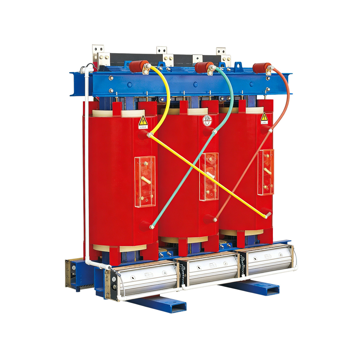
Thermal stress remains the primary killer of heavy electrical infrastructure. When engineers design or upgrade a power distribution system, selecting an inadequate thermal rating often leads to catastrophic coil failures. These failures cause unbudgeted downtime and can trigger a complete collapse of facility reliability.
In the realm of electrical engineering, thermal management dictates equipment longevity. Engineers must understand how insulation materials determine the maximum allowable operating temperature of a unit before irreversible chemical degradation occurs. This technical guide breaks down the critical standards of thermal endurance. By reviewing these engineering principles, facility managers will possess the actionable knowledge needed to specify the exact thermal ratings required for their modern grid applications.
Thermal Rating Equals Lifespan: The correct thermal barrier prevents premature coil failure by safely dissipating the immense core heat generated during voltage conversion.
Understand the Temperature Formula: A unit's total maximum operating temperature is always a strict combination of ambient air temperature, average winding rise, and a specific hot-spot allowance.
Industry Baselines are Shifting: While legacy systems utilized lower ratings, Class F at 155 degrees Celsius and Class H at 180 degrees Celsius represent the most reliable choices for modern indoor power distribution.
Application Environment Dictates Choice: Harsh industrial environments and grids dealing with inverter harmonics demand higher-tier protection, such as Class 220, to maintain optimal safety.
System-Wide Consistency is Mandatory: Auxiliary grid components must match the primary thermal ratings to ensure overall system integrity during peak electrical loads.
Unlike liquid-filled units that rely on mineral oil or silicone fluids to dissipate heat, a dry type unit is a solid-state device. It transfers electrical energy using ambient air ventilation combined with advanced solid epoxy or resin materials. This fundamental design difference completely eliminates the risk of oil leaks, chemical spills, and severe pool-fire hazards. Consequently, solid-state designs are the preferred choice for commercial high-rises, underground vaults, and environmentally sensitive areas where strict fire codes apply.
During the conversion of electrical voltage, equipment experiences unavoidable energy losses. These manifest primarily as copper I-squared-R losses in the conductive windings and iron losses, including hysteresis and eddy currents, within the magnetic core. Both forms of energy loss convert directly into thermal energy. If this heat is not properly managed through engineered cooling channels and robust materials, it will literally melt the conductive copper or aluminum. This melting instantly triggers a catastrophic short circuit.
High-grade epoxy resins, fiberglass, and aramid paper serve a critical dual purpose. First, they provide the necessary dielectric strength to prevent electrical arcing between individual winding turns. Second, they act as a robust thermal barrier. A premium barrier withstands sustained high temperatures without oxidizing, chemically degrading, or losing its mechanical integrity.
In heavy electrical infrastructure, the longevity of your equipment is directly tied to the thermal endurance of its internal components. A widely accepted engineering rule, derived from the Arrhenius equation for chemical reaction rates, states that for every 10 degrees Celsius a unit operates continuously above its rated maximum, its expected lifespan is cut by exactly half. Proper specification is the absolute bedrock of engineering Safe Dry Type Transformers. Precise specifications ensure the equipment operates reliably for its intended 20 to 30-year lifecycle without sudden dielectric breakdown.
Recent power grid trends reveal a noticeable shift in how electrical engineers specify thermal parameters. The rapid expansion of artificial intelligence data centers, electric vehicle charging infrastructures, and decentralized microgrids has fundamentally changed power consumption. Facility loads are becoming increasingly non-linear and highly unpredictable.
To combat the aggressive harmonic heating caused by these modern loads, the industry is moving rapidly away from baseline thermal ratings. Engineers are now heavily favoring high-tier Class H and Class 220 systems. Upgrading to these higher endurance levels guarantees critical operational headroom. It prevents grid bottlenecks when sudden power spikes occur, ensuring continuous operation for mission-critical facilities that simply cannot afford thermal-induced shutdowns.
Global organizations strictly standardize thermal limits to ensure cross-compatibility and safety. The mathematical formula for determining maximum operating temperature remains straightforward. You must add the ambient temperature, the average temperature rise, and the hot spot allowance to find the absolute maximum limit.
Insulation Class | Max Temp Limit | Typical Temp Rise | Best Application Scenario |
|---|---|---|---|
Class B | 130°C | 80°C | Legacy systems, small control panels |
Class F | 155°C | 115°C | Commercial buildings, HVAC systems |
Class H | 180°C | 115°C or 150°C | Heavy industry, data centers, marine grids |
Class 220 | 220°C | 150°C | Solar inverters, extreme ambient heat, heavy motors |
Class B is an older standard that is becoming increasingly rare in modern, high-efficiency power distribution. It allows for a 40-degree ambient base, an 80-degree average rise, and a 10-degree hot spot allowance. Due to its highly limited thermal capacity, Class B is generally restricted to very small control circuits or legacy equipment operating in meticulously climate-controlled rooms.
Representing a significant step up in thermal endurance, Class F serves as the baseline standard for many general-purpose commercial applications. Specifically, these systems offer an excellent balance of cost-effectiveness and reliable performance for office buildings, retail spaces, and institutional facilities where electrical loads remain relatively steady. They comfortably handle standard indoor environments without requiring expensive forced-air cooling upgrades.
Class H is widely considered the workhorse of the modern industrial electrical grid. Rated for a maximum of 180 degrees Celsius, it typically combines a standard ambient base with a 115-degree or 150-degree rise. This class is highly recommended for facilities that experience fluctuating power demands or mild harmonic distortion. For example, modern 24 kV cast resin designs utilizing Class H materials can easily support capacities up to 3150 kVA while maintaining strict IP20 or IP23 enclosure protections. This provides a robust safety margin that prevents degradation during temporary, unexpected load spikes.
Class 220 represents the absolute highest standard of thermal endurance for dry type distribution networks. Built with advanced materials like high-temperature aramid paper, it safely operates at a maximum of 220 degrees Celsius. Engineers specify this tier when designing efficient transformer solutions for extreme environments. Heavy manufacturing plants, mining operations, and specialized applications requiring the most robust thermal performance available rely heavily on this top-tier rating.
Understanding how to calculate and specify temperature rise is just as critical as selecting the thermal class itself. A mismatch in this calculation can render an expensive equipment upgrade entirely useless.
Industry standards universally set the baseline ambient air temperature at 40 degrees Celsius for a maximum 24-hour average. However, real-world conditions often deviate from this pristine laboratory baseline. Imagine a unit installed in the stifling heat of an unventilated subterranean vault, or housed in a sealed outdoor enclosure in a desert climate. Ambient temperatures in these scenarios can easily shatter that standard mark. Consequently, engineers must proactively de-rate the capacity or specify a lower temperature rise to ensure the final operating temperature never breaches the absolute maximum limit.
A coil does not heat evenly across its entire surface. While the outer layers of the winding are exposed to ambient air and cool relatively efficiently, the innermost layers trap heat deep near the magnetic core. This localized area of extreme temperature is known as the hot spot. Calculations inherently include a hot spot allowance, typically ranging from 10 to 30 degrees, to guarantee that the absolute hottest microscopic point inside the unit does not exceed the thermal breakdown threshold of the epoxy.
One of the most effective engineering strategies is specifying a high thermal class but designing the unit to operate at a much lower temperature rise. This creates a massive thermal buffer. For example, a Class 220 system running at an 80-degree rise has an extra 70 degrees of thermal headroom. This specific buffer allows the equipment to handle significant temporary overloads, such as starting massive industrial induction motors, without suffering any reduction in its expected lifespan.
Selecting the correct rating is rarely a simple decision. Procurement teams and facility managers must meticulously evaluate the specific environmental conditions, harmonic load profiles, and daily operational demands of their infrastructure.
In environments like high-rise office buildings, hospitals, and hyper-scale data centers, the primary concerns are strict fire safety, low acoustic noise, and steady voltage regulation. Because industrial HVAC systems typically climate-control these environments, Class F or Class H ratings are generally sufficient. The engineering focus here remains on utilizing equipment that eliminates fire hazards while providing clean power to sensitive IT and medical hardware.
Manufacturing facilities present a much harsher operational reality. Equipment here faces frequent power spikes, heavy motor starting currents, airborne conductive dust, and high ambient heat from nearby machinery. Standard commercial ratings often fail prematurely under these conditions. Furthermore, industrial sites frequently utilize Vacuum Pressure Impregnation or Cast Resin designs. In these robust designs, the coils are completely sealed in epoxy under a high vacuum. This manufacturing process protects the high-temperature Class H or Class 220 materials from moisture ingress and severe chemical corrosion.
The transition to green energy introduces unique thermal challenges to electrical infrastructure. Solar and wind farms rely heavily on solid-state inverters to convert direct current to alternating current. These inverters introduce high-frequency harmonic distortion into the electrical grid. Harmonics drastically increase eddy current losses, causing abnormal and aggressive heating inside the core and coils. Due to these extreme factors, specifying Renewable Energy Transformers equipped with Class 220 materials is generally considered non-negotiable. This ensures grid stability and prevents thermal breakdown in harsh, unshaded outdoor environments.
A resilient power distribution network consists of more than just the primary step-down or step-up unit. The grid relies heavily on a precise network of auxiliary metering, relay, and protection devices to ensure safe daily operation. If the main power unit is upgraded for high thermal endurance, these auxiliary components must absolutely meet similar rigorous standards.
An Electrical Current Transformer is designed to step down massive grid currents to a standard secondary output for relays and metering equipment. Because it sits directly in series with the high-power lines, it is subjected to the exact same ambient heat and load-based thermal stress as the primary system. If its thermal rating is inadequate, degradation can cause inter-turn short circuits. This leads to catastrophic metering failures, blinding protective relays, and potentially causing a localized electrical fire.
Similarly, safe voltage monitoring relies on precise potential transformers to step down high system voltages to safe metering levels. Accuracy remains the most critical metric for these devices. Excessive thermal stress can permanently alter the magnetic permeability of their core materials and degrade the dielectric strength of their delicate windings. This degradation introduces phase angle errors and ratio inaccuracies, leading to massive revenue loss in power metering and potentially unsafe grid conditions.
Procurement professionals often face the difficult dilemma of balancing upfront capital expenditure with long-term operational expenditure. While it is tempting to select a lower thermal rating to save on initial costs, heavy electrical infrastructure requires a long-term financial perspective.
It is an objective fact that higher thermal classes cost more upfront. Class 220 systems require advanced, expensive materials such as specialized high-temperature epoxies and complex vacuum manufacturing processes. However, evaluating heavy equipment based solely on its initial purchase price is a flawed procurement strategy. The Total Cost of Ownership must account for daily energy efficiency, expected lifespan, and maintenance requirements over a 30-year horizon.
Investing in higher-tier materials yields a massive return on investment over time. As mentioned earlier, buying a Class 220 system but operating it at a Class F temperature rise drastically increases its life expectancy. Because the internal barrier is never pushed to its thermal limits, it degrades at a fraction of the normal rate. In addition, units designed for lower temperature rises typically utilize larger copper or aluminum conductors. This larger conductor mass inherently lowers the internal resistance, saving thousands of dollars in wasted electricity over the unit's lifecycle.
A properly specified solid-state unit requires minimal maintenance, usually just annual visual inspections and infrared thermal scanning. Contrast this minimal upkeep with the catastrophic cost of an unexpected factory shutdown. Picture a heavy manufacturing plant grinding to a halt, filled with the acrid smell of burnt epoxy because an under-specified Class F unit blew out during a harmonic overload. The cost of lost production, emergency equipment replacement, and expedited labor will instantly dwarf any money saved during the initial purchase.
Choosing the correct thermal rating for your equipment is a critical engineering decision. It directly impacts the safety, efficiency, and longevity of your entire power infrastructure. Whether you select Class F for a standard commercial building, Class H for heavy industry, or Class 220 for a demanding renewable energy application, the decision must be based on a careful analysis of ambient temperatures, harmonic load expectations, and the physical installation environment.
We strongly advise facility managers and procurement teams to conduct a thorough thermal and harmonic audit of their specific facility needs. If you are upgrading your facility's electrical grid, explore our comprehensive catalog of high-end power solutions and auxiliary protection devices at Sline Electric, or contact our technical engineering team for a custom consultation and precise specification quote today.
Yes, this is a highly recommended engineering practice. Using a higher thermal tier in a lower temperature application extends the lifespan of the equipment significantly. It provides a much larger thermal buffer, meaning the internal materials degrade at a slower rate and can easily absorb temporary load spikes without sustaining internal damage.
Cast resin designs have their primary and secondary coils completely encased in solid epoxy resin under a high vacuum. This specific manufacturing process eliminates microscopic air pockets where partial electrical discharges can occur. It provides robust thermal insulation while simultaneously hermetically sealing the coils against moisture, conductive dust, and corrosive chemical vapors.
Standard cooling ratings are based on operation at or below 1000 meters. At higher altitudes, the ambient air is thinner and significantly less effective at dissipating heat away from the coils. To compensate for this higher temperature rise, engineers must either de-rate the equipment's capacity or choose a higher thermal class to safely accommodate the reduced cooling efficiency.
Yes. Equipment utilized in solar and wind farms must handle high-frequency harmonics generated by power inverters. These harmonics create severe excess heat in the core and windings. Consequently, they typically require higher thermal classes, like Class H or 220, alongside specialized winding designs to remain efficient and safe over their intended operational lifespan.
When equipment consistently operates above its maximum thermal limit, the internal epoxy and paper barriers begin to chemically break down and become brittle. This rapid degradation drastically lowers the dielectric strength. Eventually, the insulation fails to separate the conductive turns, resulting in a massive internal short circuit, equipment destruction, and potential fire hazards.
If your indoor facility has climate-controlled HVAC, predictable linear loads, and strict budget constraints, Class F is highly effective and safe. However, if your facility lacks dedicated air conditioning, plans to add heavy machinery in the future, or experiences frequent grid voltage fluctuations, upgrading to Class H provides the necessary engineering safety margin to prevent premature failure.