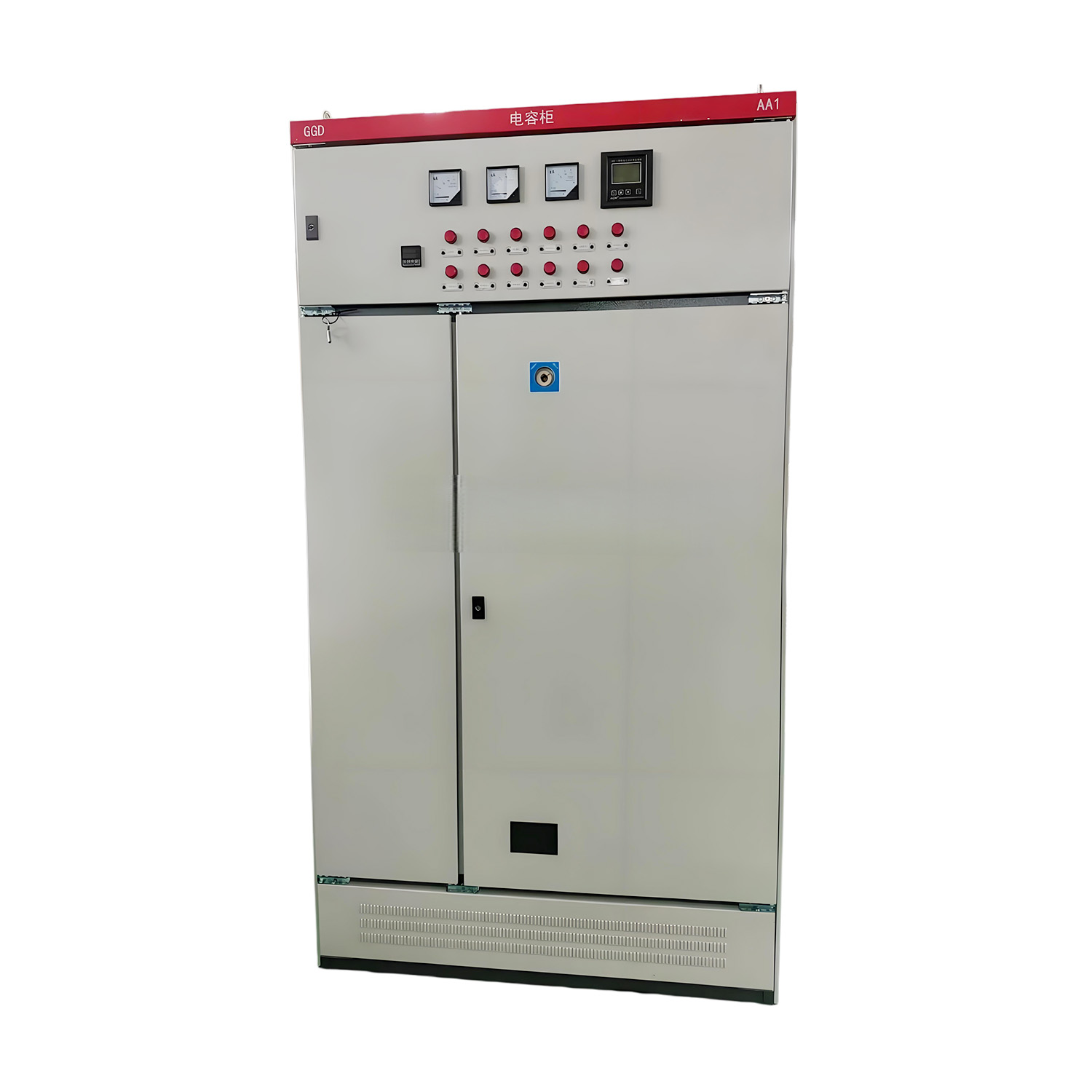
Imagine walking through your plant floor. Motors are humming, compressors cycle on and off, and automated assembly lines run at full capacity. Behind the scenes, however, fluctuating reactive power quietly inflates your utility bill and stresses your transformers. Are utility penalties for poor power factor draining your operational budget? Relying on a basic, uncalibrated setup is simply not enough in modern industrial environments. You need the precise step count for accurate load matching. Let us evaluate your load profile and select the exact configuration required to maximize efficiency.
Precision Matters: The correct step count guarantees accurate compensation. It avoids the severe risks associated with dangerous over-voltage or inefficient under-correction.
Load Variability is the Guide: Highly dynamic electrical loads demand a higher number of steps. Stable, continuous operations achieve optimal efficiency with a simpler, streamlined configuration.
Strategic Step Sizing: The smallest step size in your setup should perfectly align with the smallest reactive load variation observed in your daily power profile.
To engineer an efficient electrical network, facility managers must look past the basic premise of reactive power compensation. We must examine the mechanical and electronic execution of the system. The overall effectiveness of any setup relies heavily on its structural division. The industry commonly refers to this division as the step count.
Industrial networks do not consume reactive power at a constant, predictable rate. As heavy motors start and HVAC systems engage, the demand for kilovolt-amperes reactive fluctuates continuously. Therefore, an automatic capacitor system is never a single monolithic block. It is strategically divided into smaller, independent stages.
A central microprocessor monitors the active and apparent power across the entire network. When this controller detects a drop below a pre-set target, it commands specific steps to engage. These stages are switched using electromechanical contactors or solid-state thyristors. By dividing the total required reactive power into discrete increments, the infrastructure dynamically adjusts its output to match real-time requirements.
Selecting the correct step count is a critical engineering decision. It directly impacts operational stability, component longevity, and the financial performance of your facility.
One of the most critical secondary benefits of accurate Power Factor Correction is vastly improved voltage stability. Massive inductive loads draw heavy reactive currents, which inevitably causes localized voltage drops. Conversely, injecting too much capacitive power during a light load period triggers damaging voltage swells.
A finely tuned configuration prevents these severe spikes and dips. By making continuous micro-adjustments, the controller maintains excellent Voltage Regulation. This protects sensitive programmable logic controllers and variable frequency drives from undervoltage faults or premature degradation.
An improper step count leads to a chronic mismatch between load requirements and provided compensation. If steps are too large, the controller might refrain from engaging them to avoid overshooting the target. The facility remains under-compensated as a result, leading to persistent utility fines and wasted energy through resistive line losses.
On the other hand, if a massive step engages during a period of low demand, the network becomes over-compensated. This dangerous leading power factor generates severe overvoltage transients. It increases the risk of harmonic resonance and can cause catastrophic failure of adjacent sensitive equipment.
Before specifying equipment, engineers must conduct a rigorous assessment of the facility load profile. The step count must mirror exactly how your plant consumes electrical power.
The first diagnostic action is categorizing the operational nature of your connected machines. Facilities with continuous processes exhibit a very flat reactive power demand curve. Water treatment plants and large-scale extrusion lines fit this profile perfectly. Because the demand rarely fluctuates, these stable environments operate highly efficiently with a simple three to four step configuration.
In contrast, automotive manufacturing floors and heavy fabrication yards experience erratic, high-frequency load changes. These applications demand a much higher step count, often eight to twelve stages. This higher resolution allows the controller to make continuous micro-adjustments without over-stressing individual contactors.
Recent energy sector analyses highlight a distinct shift in power quality management. As manufacturing increasingly pivots toward heavy automation, robotics, and electric vehicle production, traditional three-step systems are rapidly becoming obsolete. Modern grids now demand high-resolution, thyristor-switched configurations. This evolution is necessary to manage highly variable loads and meet increasingly stringent utility grid codes without triggering resonance issues.
Manufacturers offer various configurations designed to meet specific industrial requirements. Understanding the practical applications of these setups is essential for smart procurement. For instance, modern low voltage systems from top-tier manufacturers like Sline Electric typically feature modular designs. They utilize self-healing metallized polypropylene film capacitors rated for 480V or 525V to handle grid fluctuations safely, with step sizes ranging from 25 to 100 kilovolt-amperes reactive.
The physical number of capacitors does not always equal the logical steps available to the controller. It depends entirely on the stepping sequence.
Stepping Sequence | Configuration Example | Total Logical Steps | Best Application |
|---|---|---|---|
Symmetrical Linear | 50 plus 50 plus 50 plus 50 | 4 Steps | Stable, predictable loads where large, equal increments are sufficient. |
Asymmetrical Binary | 25 plus 50 plus 100 plus 100 | 11 Steps | Highly variable loads. Provides maximum resolution with fewer physical components. |
Asymmetrical stepping allows a controller to combine different physical capacitor stages to create a wider variety of outputs. Specifically, this optimizes internal panel space and reduces initial financial investment while maintaining exceptional load-tracking resolution.
The selection of a step count cannot occur in a vacuum. It must be cross-referenced with the physical and electrical realities of your facility.
Modern industrial microgrids are rapidly evolving. Forward-thinking facilities are increasingly combining precise reactive power stepping with advanced Energy Storage Solutions. While battery storage systems are primarily deployed to manage active power demands and handle peak shaving, they do not efficiently handle heavy reactive power burdens.
By integrating a multi-step compensation system, the capacitor stages handle the reactive load entirely. This frees up the inverter capacity of the energy storage setup to focus on active power delivery. Furthermore, centralizing motor control and reactive power compensation through a well-engineered motor control center panel drastically reduces cable runs. It improves diagnostic accessibility and optimizes your physical floor footprint.
Even with a solid understanding of load profiles, industrial buyers frequently fall into several well-documented engineering traps.
One of the most prevalent errors is specifying a low step count for a highly variable load simply to reduce initial capital expenditure. This is a false economy. The setup will fail to track the load accurately. The facility will continue to incur utility penalties, and rapid wear on the few existing contactors will quickly negate any upfront savings.
In modern facilities heavily populated with non-linear loads like LED drivers and automated robotics, total harmonic distortion is a critical factor. Rapidly switching capacitor steps can interact with these harmonics. This creates a resonant circuit that amplifies distortion to destructive levels. If your network has high distortion, the steps must be equipped with detuned reactors to shift the resonance frequency safely below dominant harmonic orders.
Determining the precise step count, calculating the optimal reactive power per stage, and selecting between symmetrical and asymmetrical configurations is not a task for guesswork. It requires rigorous empirical data and deep electrical engineering expertise.
To ensure your investment yields maximum reliability, consult with a specialized electrical manufacturer. Sline Electric designs custom-tailored solutions that guarantee perfect voltage stability and optimal energy efficiency. Do not let poor power quality dictate your operational costs. Explore Sline Electric today to secure the exact reactive power solution your facility demands.
Calculating the size of a single step requires understanding both your total reactive power requirement and your smallest fluctuating load. As a general engineering rule of thumb, the smallest step in your system should closely match the smallest reactive load variation in your facility. For symmetrical systems, simply divide the total required reactive power by the number of steps. However, asymmetrical configurations are often used to achieve higher resolution with fewer physical components.
Yes, adding steps to an existing setup is entirely feasible, provided your initial system was designed with scalability in mind. Your intelligent controller must have unused output relays available, and there must be adequate physical space and busbar capacity within the steel enclosure. Because this involves modifying live industrial equipment, expansion must always be executed by certified professionals.
The primary difference lies in the switching mechanism and response speed. Contactor-switched steps use electromechanical relays, which are cost-effective and suited for stable loads where switching occurs infrequently. Thyristor-switched steps utilize solid-state semiconductor technology to switch stages in milliseconds. Thyristors also perform zero-crossing switching, which eliminates transient inrush currents, making them ideal for highly sensitive or rapidly fluctuating loads.
Absolutely. A higher step count provides significantly smoother and more precise adjustments to the electrical network. Utilizing only a few massive capacitor stages injects large blocks of reactive power all at once, causing sudden voltage spikes. By breaking the total requirement down into numerous smaller granular steps, the controller can gently ramp the reactive power up or down, maintaining a highly stable voltage profile.
The lifespan of switching contactors depends heavily on the load variability and the step count resolution. In a properly sized system with adequate steps, contactors typically last between three to five years. However, if the system has too few steps and constantly hunts for the correct power factor, contactors can burn out in under twelve months due to excessive inrush currents.
Yes, a properly engineered high-resolution system tracks your facility dynamic load perfectly. By injecting the exact amount of reactive power required millisecond by millisecond, it maintains your power factor well above the utility threshold. This strict compliance effectively eliminates low power factor penalties and reduces overall demand charges.
They operate synergistically to provide comprehensive power quality management. While battery banks primarily handle active power demands like peak shaving and backup power, they do not efficiently manage reactive power. By deploying a multi-step capacitor system to handle the reactive load, the battery can focus entirely on active power, drastically improving total microgrid efficiency and independence.